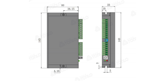
Search
Search
Confirm
Cancel
asfasfw
asfasfw

TL一BLDC48-400R

TL-BLDC24-400R is a brushless DC driver with high-performance DSP as the computing core and multi-function control method developed and produced by the same road company. The all-digital design makes it have flexible and diverse input control methods, complete software and hardware protection functions, and the driver can be connected to the computer through the RS-485 communication interface to realize parameter adjustment, protection parameters, motor parameters, acceleration and deceleration time and other parameter settings .
Retail price
0.0
Market price
0.0
Number of views:
1000
Product serial number
Category: Drive card
Quantity
-
+
Stock:
0
1
Detailed

Technical parameter specifications

project

Minimum

Typical value

Max

unit

Input voltage

14

twenty four

60

V

Output current

1


A

Undervoltage protection


VDC

Overvoltage protection


60

VDC

Speed ​​control

100

3000

30000

Rpm

weight

0.24KG

size

143 * 80 * 33 unit MM


Speed ​​mode

1: 0-5VDC analog input
2: 0-100% PWM input (PWM frequency range: [1Kz-20KHz)
3: external potentiometer speed regulation
4: set by RS 485 communication

Overcurrent protection function

When the current exceeds the working current setting value and continues for a set time, overcurrent protection is generated

Overpressure

Overvoltage protection is generated when the voltage exceeds 60v

Undervoltage

When the voltage is lower than 14v, under-voltage protection is generated

Hall anomaly

Abnormal value of Hall signal

Acceleration and deceleration time setting

The acceleration and deceleration time can be set through the software of the upper computer software

 
Digital control signal terminal
Signal

Terminal

content


power input

+

DC power input positive. (Voltage range DC24-60V)

-

The negative pole of the DC power input.


Motor connection

IN

Brushless DC motor W phase.

V

The V phase of the DC brushless motor.

U

Brushless DC motor U phase.


Hall signal

R E F-

Hall signal ground wire for brushless DC motor.

HC

Hall signal HC of the DC brushless motor.

H B

Hall signal HB of the DC brushless motor.

HE HAS

Hall signal HA of the DC brushless motor.

REF+

Hall signal power line for brushless DC motor.


control signal

SV

①External speed control potentiometer; ②External analog signal speed control input; ③PW M speed control signal input.

GND

Common port (OV reference level).

FR

When FR terminal is disconnected from GND terminal or high level input, the motor rotates forward, short circuit or low level input motor reverses.

ON

When EN terminal and GND terminal are disconnected or high level input, the motor stops running, short circuit or low level input, the motor runs

BRK

The motor stops running when the BK terminal is disconnected from the GND terminal or high level input, and the motor runs when short circuited or low level input.

A+

RS-485 communication port

B-

RS-485 communication port


output signal


SPEED

Corresponding to the running speed of the motor, the corresponding pulse frequency is output. The speed of the motor can be calculated using PG.
The motor speed
calculation formula is: N (r pm) = (F/ P) × 60
F: output pulse frequency; Hz. P: motor pole pair number: N: motor speed

Example: Motor with 4 pairs of poles
F=l sec/ 2ms =500Hz
N(r pm) = (500/4)×60 = 2500

AL

Motor or drive control fault signal output signal, which is normally 5V, and the level is OVO when a fault occurs


Download: Keyboard instruction manual_V1.0.PDF


Download: TLRVC21-200L-R manual_V1.0.PDF

Next

MORE PRODUCTS

Messages


If you have any good suggestions and comments on our company, or want to consult our products, please fill in the form below, and we will contact you at the first time!

Username used for comment:
客户留言
Description:
微信公众号
Wechat
微信公众号
Tiktok
© 2021 Dongguan Tonlo Machinery Technology Co., Ltd 粤ICP备2021136867号 Powered by 300.cn